

Shaft Alignment Training
A 60-page course book that treats alignment as a calculation: offset, angularity, shim thickness and thermal growth, with the sign conventions worked.
There is no international standard for shaft alignment tolerance, so the working rule is that acceptable offset is 110 divided by the running speed in millimetres, acceptable angularity is 75 divided by the speed in millimetres per 100 mm, and excellent is half of each. Below 600 rpm the tolerance stops tightening and is held at the 600 rpm value.
A given offset does not become any larger when the machine runs faster. Two things change instead. The coupling elements, the bearings and the seals are worked through that same offset more often in every hour the machine runs, so the cycles accumulate faster. And the parts have to be accelerated through the same displacement in less time, so the same offset generates more force. Both push the same way, which is why the permissible offset has to fall as speed rises. That single idea produces every published alignment table in the trade, and the tables differ only in where they were rounded.
Written as constants in millimetre-rpm:
| Quantity | Acceptable | Excellent |
|---|---|---|
| Offset, mm | 110 / rpm | 55 / rpm |
| Angularity, mm per 100 mm | 75 / rpm | 37.5 / rpm |
Those four numbers are common industry practice, not a standard, and they apply to short flexible couplings. Every figure the calculator prints comes from them and from nothing else, which is the only claim worth making for them.
Every figure below is the arithmetic above and nothing else.
| Speed | Offset acceptable | Offset excellent | Angularity acceptable | Angularity excellent |
|---|---|---|---|---|
| 600 rpm | 0.183 mm | 0.092 mm | 0.125 | 0.063 |
| 900 rpm | 0.122 mm | 0.061 mm | 0.083 | 0.042 |
| 1200 rpm | 0.092 mm | 0.046 mm | 0.063 | 0.031 |
| 1500 rpm | 0.073 mm | 0.037 mm | 0.050 | 0.025 |
| 1800 rpm | 0.061 mm | 0.031 mm | 0.042 | 0.021 |
| 3000 rpm | 0.037 mm | 0.018 mm | 0.025 | 0.013 |
| 3600 rpm | 0.031 mm | 0.015 mm | 0.021 | 0.010 |
Angularity is a slope, so its units are millimetres per 100 mm of axial length: 100 mm travelled along the shaft, not 100 mm of coupling diameter. Read the same way as offset it is meaningless: a slope of 0.05 says nothing until you know over what distance.
Below 600 rpm the tolerance is held at the 600 rpm row. The formula would keep granting a larger and larger allowance on a slow machine, and past a point that stops being an alignment tolerance and becomes permission to leave the machine misaligned.
A general rule like this one is the last of four places to look, not the first.
Whichever figure is used, write it on the alignment record together with where it came from. A tolerance without a source cannot be defended later, and the next person to work on the machine has no way of knowing whether to keep it.
Spacer shafts and membrane couplings are more forgiving of offset and less forgiving of angle than a short flexible coupling, and they are worked to their own numbers rather than to this rule.
The other case that falls outside the rule is any machine whose alignment target is not zero. That covers anything with meaningful thermal growth, which is most hot pumps, most compressors and most turbines. On those machines the tolerance is a band around a deliberate cold offset, not a band around zero.
Readings describe the position of the movable machine relative to the stationary one.
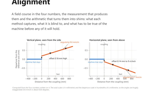
The angularity sign is the one that catches people, so it is worth stating twice: a positive result means the axis of the machine being measured rises as it goes away from the coupling. That is what makes the projection below work, because the slope has to carry the shaft further from zero as the distance to the foot grows.
Any consistent convention works, but a convention swapped halfway through a job produces shim corrections in exactly the wrong direction, and that failure looks like a measurement error rather than a bookkeeping one.
The coupling is where the tolerance lives. The feet are where the work happens, and they are not in the same place.
Where the movable shaft sits at a given foot is the offset at the coupling plus the slope carried along the shaft to that foot:
The move required is the negative of that, because the whole point is to bring the position back to zero. Positive means add shim vertically or move right horizontally; negative means remove shim or move left.
This is the step that makes a small angularity expensive. A slope that looks negligible at the coupling has been multiplied by the distance to the far foot by the time it reaches the shims, and on a long machine the far foot move is often several times the offset reading that raised the alarm.
A machine running at 1480 rpm. The near foot is 250 mm from the coupling centre and the far foot 700 mm. The readings are 0.12 mm vertical offset, 0.06 vertical angularity, −0.04 mm horizontal offset and 0.02 horizontal angularity.
The tolerances at that speed are 110 / 1480 = 0.074 mm acceptable offset, 55 / 1480 = 0.037 mm excellent, 75 / 1480 = 0.051 acceptable angularity and 37.5 / 1480 = 0.025 excellent.
| Reading | Value | Verdict |
|---|---|---|
| Vertical offset | 0.12 mm | Out of tolerance |
| Vertical angularity | 0.06 | Out of tolerance |
| Horizontal offset | −0.04 mm | Acceptable |
| Horizontal angularity | 0.02 | Excellent |
The moves follow from the offset plus the slope:
The vertical error at the coupling was 0.12 mm and the shim change at the far foot is 0.54 mm. That ratio is the normal state of affairs, and it is why alignment is judged at the coupling and corrected at the feet.
No. There is no international standard that sets a shaft alignment tolerance. What the trade uses is a family of published tables that all come from the same rule, namely that permissible offset multiplied by speed is a constant, so the tolerance tightens as running speed rises. The order of authority is the site's own alignment specification first, then the machine manufacturer, then the contract, and a published general guideline only where those three are silent. Whichever figure is used goes on the record alongside the reading, with the source it came from.
Working to the common industry rule, acceptable offset is 110 divided by the running speed in rpm, which at 1500 rpm is 0.073 mm, and excellent is half of that at 0.037 mm. Acceptable angularity is 75 divided by the speed, expressed in millimetres per 100 mm, which is 0.050 at 1500 rpm, with excellent again half at 0.025. These apply to short flexible couplings.
Offset is how far the two shaft centrelines are displaced from one another at the coupling, measured in millimetres. Angularity is how much they diverge, measured as a slope in millimetres per 100 mm of axial length, meaning 100 mm travelled along the shaft and not 100 mm of coupling diameter. A pair of shafts can be parallel but displaced, angled but crossing at the coupling centre, or both at once, and the two conditions need different corrections at the feet.
No. The published tables start at 600 rpm, and below that speed the tolerance is held at the 600 rpm value rather than being allowed to grow without limit. At 600 rpm the acceptable offset works out at 0.183 mm and acceptable angularity at 0.125 mm per 100 mm, and a machine running slower than that is worked to those same figures.
Take the offset at the coupling and add the slope carried along the shaft to the foot: the angularity divided by 100, multiplied by the distance in millimetres from the coupling centre to that foot. That gives where the movable shaft actually sits at the foot. The move is the negative of it, because the point of moving the foot is to bring that position back to zero.
The calculator gives you the number. These course books explain what the number means and how the measurement that produced it should be taken.
A 60-page course book that treats alignment as a calculation: offset, angularity, shim thickness and thermal growth, with the sign conventions worked.
45 practice questions across shaft alignment and field balancing, from shim arithmetic to two-plane vector corrections, each answer worked in full.