

Infrared Thermography Training: Category I
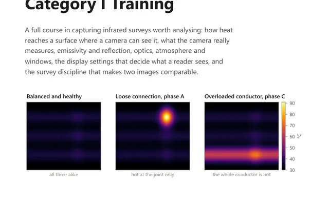
A 54-page course book for the thermographer who captures the images: how heat reaches a surface, emissivity, optics, and the conditions a survey needs.
Enter the temperature the camera reported, the emissivity it was set to, the emissivity of the surface and the reflected apparent temperature, and the calculator returns the true temperature, the size of the error, and how much a 0.05 mistake in emissivity would move the answer. On a low emissivity surface that last figure is often larger than the fault threshold being applied.
A thermal camera does not measure temperature. It measures radiance, and then it works backwards to a temperature using the emissivity it was told.
What reaches the detector from a surface is partly emitted by the surface and partly reflected from its surroundings:
received = ε × W(T_surface) + (1 − ε) × W(T_reflected)The camera runs that equation in reverse using its own emissivity setting. If that setting is not the surface’s real emissivity, the temperature it reports is not the surface’s real temperature. Setting both sides equal and rearranging for the true temperature is exactly what this calculator does:
T_true⁴ = [ ε_set × T_indicated⁴ + (ε_true − ε_set) × T_reflected⁴ ] ÷ ε_truewith every temperature in kelvin.
The fourth power is the simplification worth naming. It is exact for a detector responding across the whole spectrum, and close for a long-wave camera at the temperatures this is used at. A camera doing the sum properly integrates over its own waveband, so its answer will differ from this one in the last degree rather than in the first.
Set the emissivity too high and the camera reads low. It has assumed the surface is a good emitter, so a given amount of radiance implies a cooler surface than it should.
Set it too low and the camera reads high.
The high setting is the dangerous one, because it is also the common one. Emissivity is often left at the factory default of around 0.95, which is right for matt paint and badly wrong for bare metal. A bright copper busbar read at 0.95 comes back looking cold while carrying more current than its neighbours.
The error is proportional to the difference between the surface temperature and the reflected temperature. When those two are similar, which they are in a room at room temperature, almost any emissivity setting returns almost the right answer.
That means an emissivity setting can be wrong for years without anyone noticing, and then be wrong by 20 or 30 degrees the first time something genuinely heats up. The survey that finds nothing is not evidence that the setting is right.
Reflected apparent temperature is not air temperature, and treating it as such is the second most common error after emissivity itself.
It is measured by crumpling a piece of aluminium foil, smoothing it out loosely, placing it at the target position facing the camera and reading it with the emissivity set to 1. Whatever the camera says is the reflected apparent temperature.
Indoors, in a switchroom, it is usually close to ambient and the shortcut is harmless. Outdoors under open sky it can be tens of degrees below air temperature, and on a low emissivity surface that difference alone moves the reported temperature by more than the fault anyone is looking for.
Which part of the arriving radiance dominates is not decided by emissivity on its own. The emitted part goes with ε × T_surface⁴ and the reflected part with (1 − ε) × T_surroundings⁴, so the crossover moves with both temperatures. In the worked example below, a surface at 101 °C against surroundings at 22 °C is still emitting about 72 per cent of what arrives even at an emissivity of 0.5, and the two terms only balance near 0.28. On a surface close to the temperature of its surroundings, reflection takes over far earlier.
The working line all three Field Series thermography books draw is 0.3. Below it the reported temperature is largely a property of the surroundings whatever the surface is doing. The correction is still arithmetically valid, but it now rests on the reflected temperature being accurate, and every uncertainty in that value is amplified.
The field answer is a patch of electrical tape, matt paint or a paint marker on the surface, with the emissivity set to the patch rather than the metal. Give the patch time to reach the temperature of the material under it before reading, or you have simply measured a piece of tape.
A camera set to 0.95 reports 78 °C on an oxidised but still fairly reflective surface whose real emissivity is 0.6. The reflected apparent temperature is 22 °C.
In kelvin, the indicated temperature is 351.15 K and the reflected temperature is 295.15 K. Substituting into the equation above gives a true temperature of about 374.4 K, which is 101.2 °C.
The reading was 23 degrees low. Against any criterion written on the difference from a reference component, an error that size moves a finding several bands, and it moves it in the direction that makes a real fault look harmless.
And if the emissivity estimate of 0.6 is itself uncertain by 0.05, the answer moves by several degrees more. That sensitivity figure is the honest measure of how much the reading is worth, and it is the reason the tape exists.
The camera under-reads. It credits the surface with emitting more radiation than it actually does, so to account for the radiance it receives it concludes the surface must be cooler than it is. Setting emissivity too low has the opposite effect and the camera over-reads. The size of the error grows with the gap between the surface temperature and the reflected temperature.
It is what a perfect mirror placed at the target position would report, meaning the temperature of everything the surface can see and bounce back towards the camera. It is measured by crumpling foil, placing it at the target and reading it with emissivity set to 1. Indoors it is usually close to ambient. Outdoors under open sky it can be tens of degrees below air temperature.
Not very, and not reliably. How much of what reaches the detector was emitted rather than reflected depends on the surface temperature and the temperature of the surroundings together, not on emissivity alone, because the emitted part goes with emissivity times the fourth power of the surface temperature and the reflected part with one minus emissivity times the fourth power of the surroundings. Below about 0.3 the reported value is largely a property of the surroundings. The usual field fix is a patch of matt tape or high emissivity paint, read once the patch has reached the temperature of the surface beneath it.
Barely, and that is exactly why the mistake survives. When the surface and its surroundings are at similar temperatures, the radiance the camera receives is nearly the same whatever fraction of it is emitted and whatever fraction is reflected. Almost any emissivity setting returns almost the right answer. The error only opens up when something is genuinely hot, which is when it is being relied on.
Yes, if the reflected apparent temperature at the time is known, and many cameras store enough radiometric data in the image to allow the setting to be changed in software later. Working from the reported temperature alone, the correction rebalances the radiometric equation for the true emissivity. It is exact in arithmetic and only as good as the reflected temperature it is given.
The calculator gives you the number. These course books explain what the number means and how the measurement that produced it should be taken.
A 54-page course book for the thermographer who captures the images: how heat reaches a surface, emissivity, optics, and the conditions a survey needs.
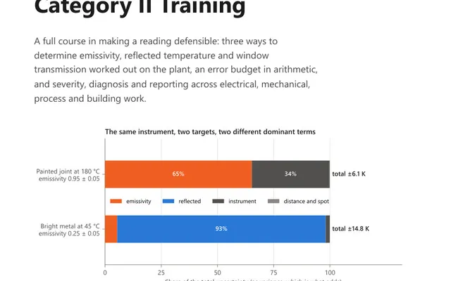
A 57-page course book on turning a thermal image into a defensible measurement, with emissivity determined on the surface and the error budget worked.
44 practice questions on capturing a survey worth analysing, from emissivity and reflection to optics and spot size, each answer worked in full.