

Vibration Analysis Training: Category II
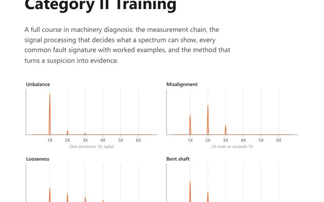
An 88-page course book on vibration diagnosis: which fault produces which pattern, what phase adds, and how to disprove an answer before reporting it.
Enter the drive and the calculator returns every frequency the machine is entitled to produce: gear mesh and hunting tooth, belt frequency, motor slip and pole pass, or blade pass. Once those are on the page, everything else in the spectrum is either a bearing or a fault.
An unfamiliar spectrum is mostly a list of peaks with no names. Some of them are there because of how the machine was designed, and no amount of maintenance will remove them. Working out which ones those are is the fastest way to shrink the problem, because whatever is left over is the part worth investigating.
The calculation costs nothing and the information is on the nameplate, the gearbox data plate or the belt itself.
Gear mesh frequency is the tooth count multiplied by the speed of the shaft carrying that gear:
The mesh frequency is the same number computed from either gear, which is a useful check: if the two sides disagree, one of the tooth counts is wrong.
What tells you something is not the mesh frequency itself but the sidebands around it. Sidebands spaced at input shaft speed put the fault on the input gear. Sidebands spaced at output shaft speed put it on the output gear. That single observation resolves most gearbox diagnoses without opening anything.
Hunting tooth frequency is the slow one. It is the rate at which a given tooth on one gear meets a given tooth on the other, and it usually sits well below one hertz. It only becomes audible when both gears are damaged: the two faults coincide at that rate and produce a growl once every several revolutions, which operators describe long before an analyst finds it in a spectrum.
Belt frequency is always below shaft speed, because the belt is longer than the pulley it wraps. A defect in the belt, a crack, a hard spot, a joint, strikes each pulley once per belt revolution, so on a two pulley drive the second harmonic often dominates. When a belt problem shows up in a spectrum, twice belt frequency is usually the first peak to appear.
Two things here catch people out. The first is that the running speed must be measured, not taken from the nameplate: slip changes with load, and slip is the whole quantity being computed. A speed at or above synchronous speed is not a slow motor, it is an unmeasured one, and the calculator refuses it rather than printing a negative slip.
The second is that pole pass frequency almost never appears as a peak of its own. It is a sideband spacing, and which peak it sits around is what names the fault:
Because pole pass frequency is a fraction of a hertz, seeing any of those sidebands is a resolution problem rather than a range problem. Raising the line count is what finds them. Raising Fmax does the opposite.
Twice line frequency, 100 Hz on a 50 Hz supply and 120 Hz on 60 Hz, is a separate matter. It is electrical, it does not move with load or speed, and switching the supply off is the test: a peak that disappears the instant power is cut is electrical, and one that coasts down with the rotor is mechanical.
Every fan and pump produces it, generated by each blade passing the cutwater or the housing tongue. A rise in blade pass amplitude is usually not a blade problem. It is a clearance problem, a flow problem, or something loose in the flow path. Check the amplitude against the machine’s own history before anyone opens a casing.
A gearbox with a 23 tooth pinion driving a 76 tooth wheel, input shaft at 1480 rpm.
The input shaft frequency is 1480 ÷ 60 = 24.667 Hz. Gear mesh frequency is 23 × 24.667 = 567.33 Hz. The output shaft turns at 24.667 × (23 ÷ 76) = 7.4649 Hz, which is 448 rpm.
23 is prime and does not divide 76, so the greatest common divisor is 1 and hunting tooth frequency is 567.33 ÷ (23 × 76) = 0.325 Hz. A tooth pair repeats once every three seconds or so.
Now set an Fmax high enough to see three harmonics of the mesh, which is 1702 Hz, and a line count fine enough to resolve sidebands spaced at 7.46 Hz around them. That second requirement, not the first, is what decides the setup.
A frequency a machine generates because of the way it is built rather than because something is wrong with it. Gear teeth meshing, a belt coming round, blades passing a housing tongue and the magnetic field of a motor all produce one. A healthy machine shows its forcing frequencies every day, so finding one proves nothing. What matters is the amplitude changing, and what appears around it.
Multiply the number of teeth on a gear by the rotational speed of the shaft that carries it, in revolutions per second. A 23 tooth pinion on a shaft turning at 1480 rpm gives 23 times 24.667, which is 567.33 Hz. The answer is the same from either side of the mesh, because the two gears engage the same number of teeth per second whichever one you count from.
It is the rate at which one particular tooth on a gear meets one particular tooth on its mate, found by multiplying gear mesh frequency by the greatest common divisor of the two tooth counts and dividing by their product. It is usually well below one hertz. It matters when both gears carry damage, because the two damaged teeth meet at that rate and produce a heavy beat once every several revolutions.
Because a belt is longer than the circumference of the pulley driving it, so it takes more than one pulley revolution to come round once. Belt frequency is pi times the pulley diameter times shaft speed in revolutions per second, divided by the belt length. Since a belt defect strikes both pulleys on a two pulley drive, twice belt frequency is often the larger peak and the one that shows first.
Slip frequency multiplied by the number of motor poles. Slip frequency is the difference between synchronous speed and actual running speed, expressed in hertz, and synchronous speed is 120 times line frequency divided by the pole count. On a healthy motor the result is a fraction of a hertz, and it rarely appears alone. Broken or cracked rotor bars show it as sidebands around running speed. Dynamic rotor eccentricity shows it as sidebands around twice line frequency. Rotor slot pass carries sidebands of its own, and those are spaced at twice line frequency rather than at pole pass.
Because there is nothing to calculate from it. An induction motor has to turn slower than its magnetic field: without that difference there is no relative motion, no induced rotor current and no torque. A speed at or above synchronous gives a slip of zero or less, and a negative pole pass frequency is an arithmetic result rather than a machine. It nearly always means the speed came off the nameplate instead of a tachometer, and slip is precisely the quantity being computed here.
The calculator gives you the number. These course books explain what the number means and how the measurement that produced it should be taken.
An 88-page course book on vibration diagnosis: which fault produces which pattern, what phase adds, and how to disprove an answer before reporting it.
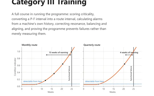
A 56-page course book on running the programme: criticality scoring, the P-F interval, and alarms calculated from the machine's own history, not a table.

42 practice questions on running a vibration programme, from criticality and the P-F interval to alarm arithmetic, each answer worked rather than lettered.