

Field Balancing Training
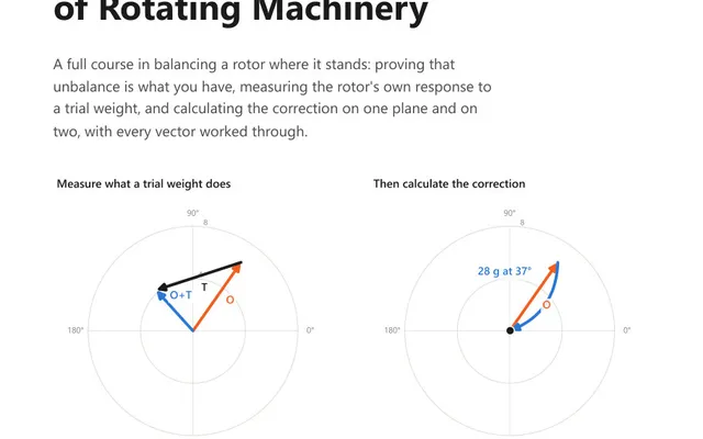
A 56-page course book that works field balancing as vector arithmetic, on one plane and on two, for the analyst who has to correct a rotor in place.
A balance quality grade fixes the product of permissible eccentricity and angular velocity, so the permissible residual unbalance is the grade divided by the angular velocity, multiplied by the rotor mass. The answer arrives in gram millimetres, which no scale reads, so the useful last step is dividing by the radius you can reach to get a weight in grams.
ISO 21940-11, which superseded ISO 1940-1, sorts rotors by what they are and gives each family a grade written as G followed by a number. That number is not a tolerance by itself. It is the permissible specific unbalance multiplied by the angular velocity at service speed, expressed in millimetres per second.
Which grade a given machine is entitled to is part of the standard, and this page does not reproduce that assignment. The calculator offers the G series so that it has something to compute with; deciding which member of the series applies to your rotor is a question for the standard, for the machine builder, or for the machine’s own history, in that order.
Because speed sits inside the product, the same grade is a looser requirement on a slow rotor than on a fast one. Double the service speed and the permissible eccentricity halves. The same fan rotor balanced to G 6.3 is allowed twice as much residual at 740 rpm as it is at 1480 rpm, and both are correct.
With a grade G in millimetres per second, a service speed n in rpm and a rotor mass m in kilograms:
r in millimetres: U_per / r, in gramsThe thousand in the second line carries millimetres to micrometres. There is a unit identity worth knowing, because it saves a conversion every time: one micrometre of eccentricity is one gram millimetre of unbalance per kilogram of rotor. The same number reads both ways.
The grades run 0.4, 1, 2.5, 6.3, 16, 40, 100, 250 and 630, each roughly two and a half times the one before it. That ratio is the thing to notice: one step is a factor of two and a half in permissible residual, which is a real change in how much work a field balance takes, and it is worth being sure the tighter grade is the one the machine is entitled to before adopting it.
Which grade goes with which kind of machine is set out in ISO 21940-11 and is not reproduced here. Take it from the standard. Where the machine builder states a residual unbalance of its own, that figure governs and the grade does not enter. Where the machine has run smoothly for years at a known residual, that history is evidence too.
A disc-shaped rotor has one correction plane. Anything long enough to carry a couple has two, which covers most machines.
Where a rotor has two correction planes placed roughly symmetrically about its centre of gravity, half the permissible unbalance goes in each plane, and that is what the calculator assumes when two planes are chosen. Where the planes are not symmetric, the standard gives each plane a share proportional to the other plane’s distance from the centre of gravity, because unbalance in the plane nearer the centre of mass has less leverage and matters less. That proportional rule taken alone runs to the extreme, handing one plane the entire allowance when the centre of mass sits over it, so the standard also bounds how far the split may be pushed. Read the bounds from the standard and apply them to the shares the rule gives, particularly on a strongly asymmetric rotor.
The permissible unbalance is a moment, and a moment is only a weight once you name a radius. Halving the radius doubles the mass you have to fit, and the radius that matters is the one at which a weight can genuinely be attached: a bolt circle, a backplate, a fan hub. Using the outer diameter of the rotor because it is the number on the drawing produces a tolerance that looks tighter than the one you are actually working to.
A 120 kg fan rotor running at 1480 rpm, balanced to G 6.3, with correction weights attached at a 200 mm radius, in two planes.
Twelve grams in each plane is the target, and holding the result in your hand as a weight rather than as a moment is the best sanity check the method offers. If a rotor of this size returns a fraction of a gram, or a figure in kilograms, something has been entered in the wrong unit before the arithmetic ever ran.
Where the machine builder states a residual unbalance, that number governs. Where the machine has a service history of running smoothly at a particular residual, that history is better evidence than any grade.
The grade is also not the only criterion, and it is sometimes not the binding one. A rotor can meet its balance grade and still exceed the machine’s vibration acceptance limit, because the reading contains everything that is not unbalance as well. Where both apply, both have to be met, and they are answering different questions: one about the rotor, one about the machine.
Balancing tighter than the grade requires is time spent buying nothing. It is also where a balance job stops converging, because past the residual the machine can hold, what remains in the reading is no longer unbalance. It is runout, a loose foot, a bent shaft, or a support that moves under load. A rotor that refuses to come down however carefully the weights are placed is usually saying that the vibration left in it was never unbalance in the first place.
G 6.3 means that the permissible specific unbalance multiplied by the angular velocity comes to 6.3 millimetres per second at service speed. The grade is that product, not a tolerance on its own. Because speed sits inside it, the same grade permits a coarser balance on a slow rotor than on a fast one, and the permissible eccentricity halves every time the running speed doubles.
Divide the grade by the angular velocity to get the permissible eccentricity, then multiply by the rotor mass. With G in millimetres per second and angular velocity in radians per second, permissible eccentricity in micrometres is G times 1000 divided by angular velocity, where angular velocity is 2 pi times rpm divided by 60. Multiplying that by the rotor mass in kilograms gives permissible unbalance in gram millimetres.
ISO 21940-11 assigns machine types to grades, and that assignment is the standard's rather than something to be taken from a web page. The order of authority is the machine builder's stated residual unbalance first, then the grade the standard assigns to the machine type, then the machine's own service history of running smoothly at a particular residual. This calculator lets you choose a grade because it cannot compute without one, and it takes no position on which grade your machine is entitled to.
For a rotor whose two correction planes are roughly symmetric about its centre of gravity, half the permissible unbalance is allowed in each plane, which is what this calculator assumes. Where the planes are not symmetric, ISO 21940-11 gives each plane a share proportional to the other plane's distance from the centre of gravity, and it also bounds how far that split may be pushed so that a plane is never left with nothing. The bounds are in the standard, and a strongly asymmetric rotor has to be checked against them before the split is used.
Divide the permissible unbalance in gram millimetres by the radius in millimetres at which a weight can actually be attached, which gives a mass in grams. A tolerance of 4878 gram millimetres is 24.4 grams at a 200 mm radius but only 12.2 grams at 400 mm. The radius has to be the one a weight can really be fixed at, not the outside diameter of the rotor.
The calculator gives you the number. These course books explain what the number means and how the measurement that produced it should be taken.
A 56-page course book that works field balancing as vector arithmetic, on one plane and on two, for the analyst who has to correct a rotor in place.

45 practice questions across shaft alignment and field balancing, from shim arithmetic to two-plane vector corrections, each answer worked in full.
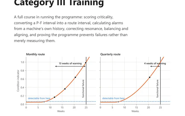
A 56-page course book on running the programme: criticality scoring, the P-F interval, and alarms calculated from the machine's own history, not a table.