

Field Balancing Training
A 56-page course book that works field balancing as vector arithmetic, on one plane and on two, for the analyst who has to correct a rotor in place.
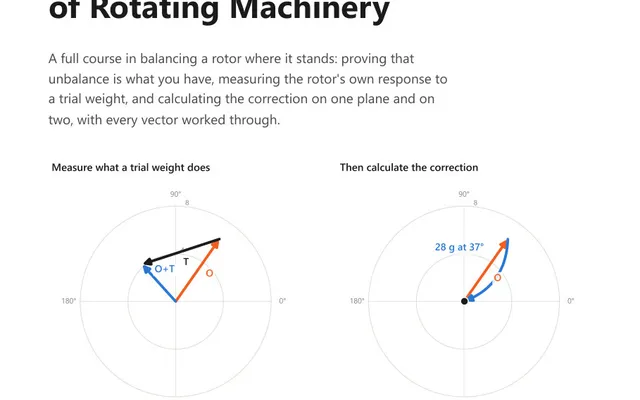
Enter the vibration amplitude and phase from an original run and from a run with a known trial mass fitted, and the vector difference between them gives the correction mass and the angle to put it at. The whole method rests on one idea: what the trial mass did on its own is the difference between the two readings, and once you know that, you know what any mass will do.
Both readings are vectors. An amplitude A at a phase angle θ becomes a pair of components:
Call the original run O and the trial run T, both converted that way. Then:
E = T − O, component by componentE| divided by the trial mass, in vibration units per gramE minus the angle the trial mass was fitted atO| / |E|E round to the direction of −OThe last line is the one worth reading twice. The correction has to act in the direction opposite the original reading. The trial mass acted in the direction of E. So the trial mass is stepped round by exactly the angle that carries E onto −O, and scaled so that its effect matches the size of the original reading.
It is a magnitude and an angle together, and both halves are needed. The magnitude says how much vibration one gram produces. The angle says how far round from the weight the response appears, which on one rotor can be nearly opposite the weight and on another almost in line with it. A magnitude on its own will size a correction and cannot place it.
That pair is what the trial run exists to obtain, and it is what makes the second correction cheap. If the check run leaves a residual R, the trim is one calculation rather than another trial weight and another two runs:
R| divided by the coefficient magnitudeR, plus 180 degrees, minus the coefficient angleThe correction already fitted stays where it is; the trim is added to it. On a rotor with fixed weight positions, resolve the small vector onto the two nearest available positions. Write the coefficient into the record with the reference mark and the direction angles increase in, because it is the most valuable line on the sheet and the one most often left off. It belongs to that machine at that speed in that plane, and next year’s balance can start from it.
This is where single plane balancing goes wrong far more often than the arithmetic does.
Mass angles and phase angles must be measured in the same rotational direction, and from the same reference mark. Most instruments read phase lag, which increases against rotation, so on most jobs mass angles are stepped off against rotation too. Nothing in the calculation can tell which convention is in use. An angle comes back in whichever convention it went in as.
The practical rule is to pick a convention before the first run, mark the rotor with a real reference mark rather than a remembered one, and step off both the trial mass and the correction in that same direction from that same mark. If the correction makes the vibration worse by roughly the amount it should have improved it, the usual cause is a correction fitted the wrong way round the rotor.
A trial run has to move the reading by at least 30 percent in amplitude or 30 degrees in phase. Below that the calculator says so, because a trial that barely moved the needle is a failure rather than a cautious choice.
The reason is arithmetic rather than convention. The trial effect is computed as the difference between two readings, and the machine’s run to run scatter sits in both of them. Suppose a rotor answers a weight at 0.148 mm/s per gram and the scatter measured across repeat runs is 0.35 mm/s. A 5 g trial gives a response of 0.74 mm/s, and the scatter sits on it at an unknown angle, so the worst case angular error in the coefficient is arcsin(0.35 / 0.74) = 28 degrees. A correction of the right size fitted 28 degrees out leaves 2 sin(14 degrees) = 0.485, so 49 percent of the original vibration survives a job otherwise done perfectly. A 25 g trial gives 3.70 mm/s, an angular error of 5.4 degrees, and a residual of about 9 percent.
So the 30 percent figure is a stand-in for the real requirement, which is that the trial effect be several times the scatter you measured on that machine. Where the scatter is known, use it; where it is not, the 30 percent is the guideline to work to.
Two explanations cover almost every failed trial run. Either the trial mass was too small, in which case fit a larger one and repeat, or the vibration at 1x is not unbalance, in which case no trial mass will move it. A bent shaft, a soft foot, a cracked rotor, a resonance near running speed or a coupling problem can all put energy at 1x and none of them responds to a weight.
Single plane balancing corrects a static unbalance. It cannot do anything about a couple, because a couple needs two corrections in opposite directions at two axial positions and single plane has only one.
Which of the two a rotor has is settled by measurement, not by its proportions. Take a 1X amplitude and phase reading at each bearing, in the same direction, at the same speed, with the same reference mark, and subtract one phase from the other.
| Phase difference between the bearings | What the rotor is doing | Correction |
|---|---|---|
| Near 0 degrees | Static unbalance: the mass centre is displaced but the axis has not tilted | One plane, at or near the centre of mass |
| Near 180 degrees | Couple unbalance: two equal heavy spots half a turn apart, rocking the rotor about its centre | Two planes, equal and opposite |
| Anywhere between | Dynamic unbalance, which is what real rotors have | Two planes, calculated |
A between-bearings fan reading 4.6 mm/s at 62 degrees on bearing A and 4.2 mm/s at 238 degrees on bearing B has a phase difference of 176 degrees. That is within 4 degrees of a straight reversal, so the forces at the two ends very nearly cancel and what is left is a moment. A single weight in one plane produces a force through that plane, which cannot cancel a moment: it would pull one bearing down and push the other up. Two planes, and the five minutes spent taking the second phase reading saved the afternoon.
The symptom to watch for on a long rotor is that split result: one bearing improves and the other gets worse. That is a couple being uncovered, not a correction going astray, and adding more weight in the same plane will make the split wider.
An original run of 6.4 mm/s at 120 degrees. A 10 g trial mass is fitted at 0 degrees, and the machine now reads 4.1 mm/s at 35 degrees.
First, the trial run is usable: the amplitude moved from 6.4 to 4.1, which is 36 percent, and the phase moved 85 degrees. Either one on its own would have cleared the bar.
As components, the original run is (−3.20, 5.54) and the trial run is (3.36, 2.35). The trial mass effect is the difference, (6.56, −3.19), which has a magnitude of 7.29 and points at 334.1 degrees.
So with the trial mass removed, fit 8.77 g at 325.9 degrees. If the trial mass is staying on, the extra weight needed is the vector difference between that correction and the 10 g already sitting at 0 degrees, which comes to 5.62 g at 240.9 degrees.
Both routes land on the same total correction. Which one you use is a question of whether the trial mass comes off easily, and on a tack welded weight it usually does not.
Suppose the check run then reads 0.5 mm/s at 40 degrees. That is a 92 percent reduction, and if it is not good enough the trim needs no further trial weight: 0.5 / 0.729 = 0.69 g, at 40 + 180 − 334.1 = −114.1, which is 245.9 degrees. Add that to what is already fitted. This is the whole return on measuring the coefficient properly, and it is only available because the angle was written down alongside the magnitude.
A first run records vibration amplitude and phase. A known trial mass is then attached at a known angle and the run is repeated. Subtracting the first vibration vector from the second leaves the effect of the trial mass alone, which gives both how much vibration one gram produces and the direction in which one gram acts. The correction is the mass that produces the same effect in the opposite direction to the original reading.
In the same rotational direction as the phase readings, and from the same reference mark. Most instruments read phase lag, which increases against rotation, so mass angles are normally stepped off against rotation as well. Nothing in the arithmetic can detect which convention is in use, so a solved angle comes back in whichever convention was fed in. Mixing the two puts the correction weight in the wrong place by a predictable but useless amount.
By measurement, before any trial weight exists. Take a 1X amplitude and phase reading at each bearing, in the same direction, at the same speed, from the same reference mark, and subtract one phase from the other. A difference near zero degrees means both ends are moving together, which is static unbalance and a one plane job. Near 180 degrees the ends are moving in opposition, which is couple unbalance and needs two planes. Anything in between is dynamic unbalance, the general case on real rotors, and it needs two planes as well. The reading takes five minutes and it saves an afternoon spent moving one weight around a rotor that cannot be fixed with one weight.
When the two bearings are not in phase. Single plane balancing corrects static unbalance and can do nothing about a couple, because a couple needs two corrections in opposite directions at two axial positions. The test is the phase difference across the bearings rather than the shape of the rotor. On a long rotor a single plane correction usually improves one bearing and makes the other worse, and that split result is what an unasked phase question looks like after the fact.
It means the trial run has failed and the solution cannot be trusted. A trial run is only usable when it moves the reading by at least 30 percent in amplitude or 30 degrees in phase, and the requirement behind that figure is that the trial mass effect be several times the run to run scatter measured on that machine, because the effect is a difference between two readings and the scatter is present in both of them. Fit a larger trial mass and repeat. If a larger mass still will not move the reading, the vibration at 1x is not unbalance.
Not necessarily. The correction mass and angle are calculated on the assumption that the trial mass has been taken off. If the trial mass has been tack welded and removing it costs another shutdown, the alternative is the vector difference between the wanted correction and the trial mass already fitted, which is an additional weight at its own angle. Both routes end at the same total correction.
The calculator gives you the number. These course books explain what the number means and how the measurement that produced it should be taken.
A 56-page course book that works field balancing as vector arithmetic, on one plane and on two, for the analyst who has to correct a rotor in place.
45 practice questions across shaft alignment and field balancing, from shim arithmetic to two-plane vector corrections, each answer worked in full.